Rain loads are the most commonly skipped load type in structural practice — even in the Southeast and Southwest, where they are the dominant weather-driven roof load. FM Global's loss data from 2007 to 2017 found that rain-related structural losses occurred 50% more frequently than snow-related losses, and rain losses in Texas and Arizona roughly equaled snow losses in New England.[1] A survey at a large Northeast engineering firm found that the majority of respondents did not routinely calculate rain loads in heavy-snow regions, relying on snow load to bound the design.[1]
ASCE 7 does not support that assumption. Section 8.2 (all editions) requires each portion of a roof to be designed to sustain accumulated rain load assuming the primary drainage system is blocked — and ASCE 7-22 raised the bar further, adding a third load term to the equation and introducing explicit criteria for which secondary drainage systems actually qualify for structural loading purposes.[2] For flexible steel framing, the ponding term alone can increase rain load by 50% or more on a standard joist bay.
Prose has a dedicated rain load module built for this calculation. It identifies the qualifying SDSL under ASCE 7-22 Section 8.2, computes , , and for each roof bay independently, handles overflow dam drains, rectangular scuppers, and circular scuppers, and outputs a code-referenced report with every calculation step cited — across editions 7-10, 7-16, and 7-22. That said, you need to understand the provisions to know whether any output is right. That's what this article covers.
The Rain Load Equation Across Editions
In ASCE 7-10 and ASCE 7-16, the design rain load is:[2,3,4]
where:
- = rain load on the undeflected roof (lb/ft²)
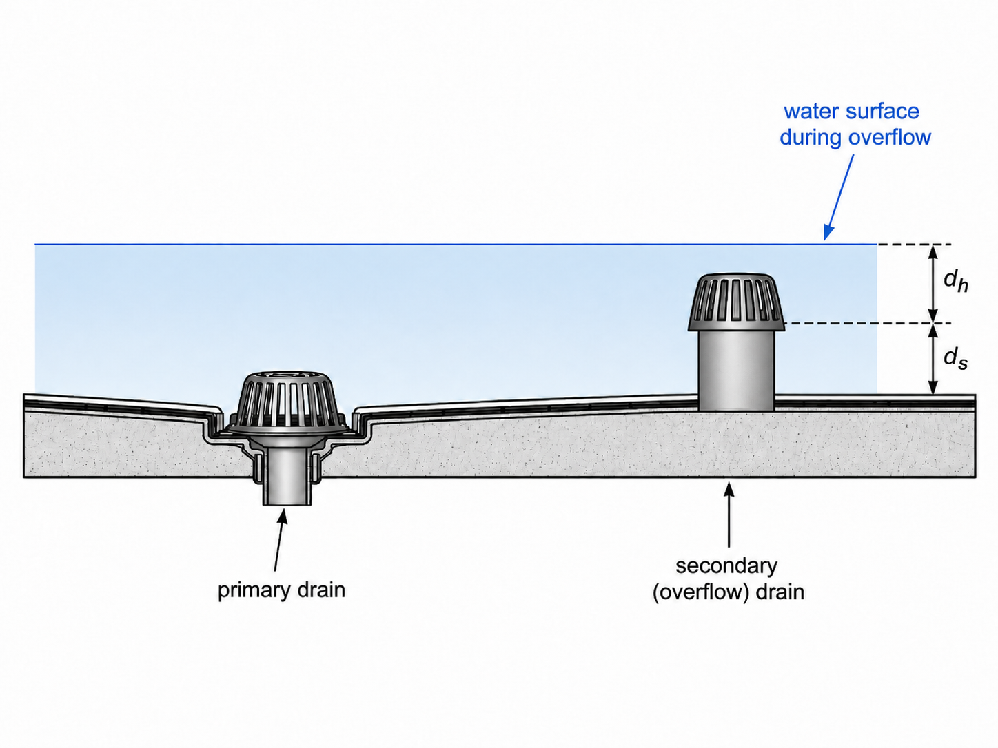
- = static head (in.)
- = hydraulic head (in.)
The factor 5.2 is a unit conversion — water weighs 62.4 lb/ft³, and per inch of depth. It is not a safety factor.
In ASCE 7-22, the equation becomes:[2]
ASCE 7-22 Eq. 8.2-1
where:
- = rain load on the undeflected roof (lb/ft²)
- = static head (in.)
- = hydraulic head (in.)
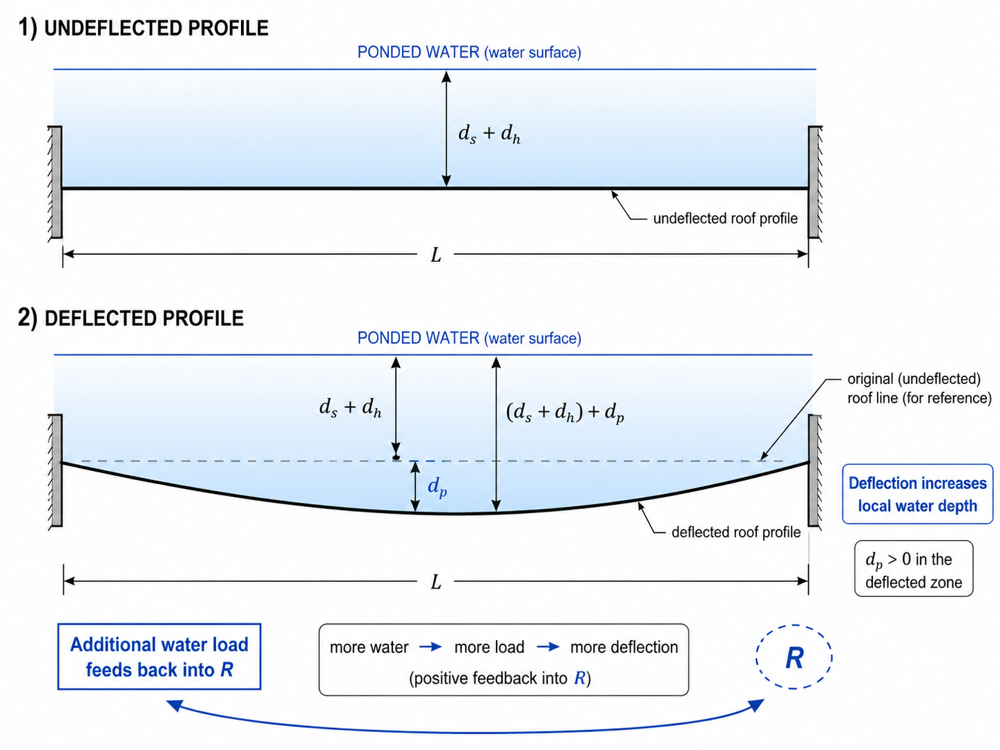
- = ponding head (in.) — depth of water due to roof deflections under unfactored rain load and unfactored dead load
In ASCE 7-16, ponding was a separate stability check (Section 8.4) requiring demonstration of adequate stiffness and strength, but the ponding contribution was not added to directly. In ASCE 7-22, is part of the load equation itself. As ASCE 7-22 Commentary C8.2 states:[2]
"The definition of rain load was changed in the 2022 edition of the standard to include the additional load due to ponding. This eliminates the need to perform a separate ponding instability check, however, the effects of ponding need to be explicitly included in the rain load."
The magnitude of that change is not subtle. The Commentary's own worked example — a standard structural steel bay — produces a ponding amplification factor and a rain load of 44 psf versus 26 psf without ponding, a 69% increase.[2] The full calculation using this article's example geometry follows below. Omitting on a flexible long-span steel joist roof is not a conservative simplification.
Edition note: is required only by ASCE 7-22 Eq. 8.2-1.[2] Projects governed by ASCE 7-16 or ASCE 7-10 use ; ponding instability is a separate check per ASCE 7-16 Section 8.4[3] or ASCE 7-10 Section 8.4.[4] AISC 360-2022 removed Appendix 2 (ponding provisions) — the current reference for ponding analysis of structural steel is AISC/SJI Design Guide 40 (2024).[5] Not all jurisdictions have adopted ASCE 7-22; confirm your governing edition before determining whether applies.
Step-by-Step: Calculating R
Step 1 — Identify the Qualifying Secondary Drainage System
This is the step that changed most significantly between editions — and where ASCE 7-22 is most explicit.
In ASCE 7-10, the standard required a secondary drainage system at a higher elevation for controlled flow roofs, but provided no definition of what qualified as a "secondary drainage system" for structural loading purposes.[4] What counted was left to engineering judgment.
In ASCE 7-16, definitions were added — PONDING, PONDING INSTABILITY, PRIMARY DRAINAGE SYSTEM, SECONDARY DRAINAGE SYSTEM — and the requirement that secondary drain lines be separate from primary lines was stated more explicitly.[3] But the standard still did not address the structural loading implications of controlled flow heads on secondary systems, secondary inlets at nearly the same elevation as the primary, or co-piped primary and secondary systems. Those ambiguities remained judgment calls.
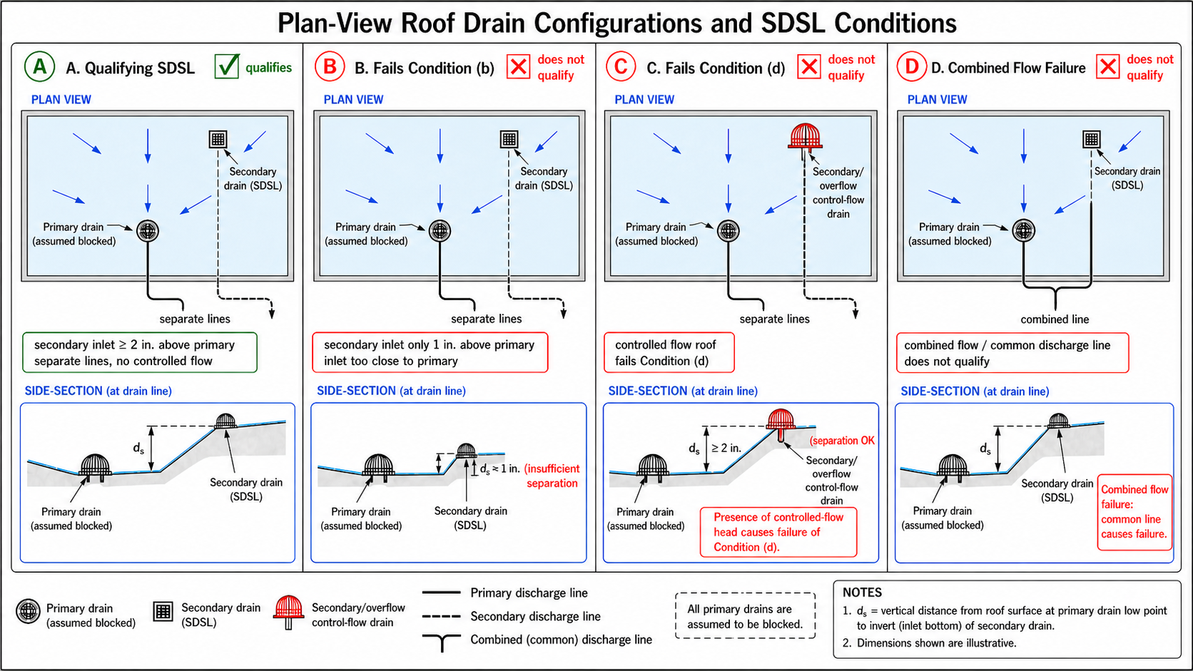
In ASCE 7-22, that judgment was replaced with four explicit conditions.[2] Section 8.2 now identifies four categories of secondary systems that are assumed blocked for structural loading purposes — in addition to the primary:
(a) The primary drainage system.
(b) Secondary drainage systems with an inlet vertically separated from the primary inlet by less than 2 in. (51 mm).
(c) Secondary drainage systems that share drain lines with the primary drainage system.
(d) Secondary drainage systems with controlled flow roof drains.
The system that remains after filtering through (a)–(d) is the Secondary Drainage System for Structural Loading (SDSL) — a term introduced in ASCE 7-22. Its inlet elevation sets . Any secondary or overflow drain designated by the MEP engineer that fails one of these conditions is assumed blocked and cannot be the SDSL. The next qualifying point of discharge becomes the structural loading basis.
This explicitness matters in practice. Before 7-22, engineers frequently accepted whatever system the MEP called "secondary" as the structural loading basis. Now the code makes that determination a four-condition threshold, not a label. As ASCE 7-22 Commentary C8.2 states:[2]
"It is possible that a drainage system that is designated as a secondary or emergency overflow drain, by the architect or mechanical (plumbing) engineer, is required to be assumed to be blocked, per Section 8.2. Such a drainage system cannot serve as the SDSL."
Controlled flow heads are the most common trigger. In some jurisdictions, ordinances limit stormwater release rates and controlled flow drains are used on nearly every commercial roof. Under 7-22, every one of those drains — primary and secondary — is assumed blocked. The SDSL becomes the parapet overflow point, and is the parapet height. On a typical commercial building with a 6-in. parapet, that produces before — a substantially higher load than a 3-in. SDSL inlet would generate.
On buildings with multiple roof bays — each with different tributary areas, drain types, and inlet elevations — this determination must be made per bay. This is exactly where rain load documentation breaks down in practice: one bay gets a proper SDSL analysis; others get a single governing value copy-pasted across the whole roof.
Prose's rain module evaluates each bay independently. You define the drain configuration per bay — drain type, standpipe or scupper size, inlet elevation relative to the primary, whether controlled flow is in play — and Prose runs the ASCE 7-22 Section 8.2 conditions against each one, sets at the correct SDSL for that bay, and carries the result forward into the full calculation. The output is a code-referenced report where each bay's SDSL determination is documented separately, with the governing section cited. That's the format a reviewer expects to see.
Edition note: The SDSL concept and the four explicit blocked-system conditions (a)–(d) are new to ASCE 7-22 Section 8.2.[2] ASCE 7-16 required separate drain lines and prohibited controlled flow drains on secondary systems (Sections 8.3 and 8.5[3]) but did not enumerate when secondary systems are structurally assumed blocked. ASCE 7-10 was even less prescriptive.[4] The progression from judgment to explicit criteria across these three editions is meaningful — and the gap between what an MEP-designated "secondary" drain is and what the SDSL is under 7-22 is where under-designed rain loads originate.
Step 2 — Determine Static Head ()
Static head is the depth from the undeflected roof surface to the inlet of the qualifying SDSL.[2] For a secondary drain pipe, is measured to the top of the pipe inlet. For a scupper, is measured to the bottom of the scupper opening.
This is a geometry question, not a calculation. Get it from the drain detail or drainage plan.
Step 3 — Determine Hydraulic Head ()
Hydraulic head is the water depth above the SDSL inlet required to pass the design flow rate — not a fixed constant. It depends on drain type, size, and flow rate.
The design flow rate is (ASCE 7-22 Commentary C8.2[2]):
where:
- = design flow rate (gal/min)
- = tributary roof area (ft²)
- = design rainfall intensity (in/hr) for the 15-minute duration storm[6]
For rainfall intensity, use the ASCE 7 Hazard Tool.[7] Enter your project location and Risk Category and it returns the 15-minute design storm intensity at the correct return period directly.
Edition note: ASCE 7-22 Table 8.2-1 introduced risk-category-dependent return periods.[2] Risk Category III requires a 200-year return period; Risk Category IV requires 500 years. ASCE 7-16 and ASCE 7-10 use 100 years for all Risk Categories.[3,4] The ASCE Hazard Tool handles the return period selection when you specify your Risk Category.[7]
Once you have , look up from the Commentary hydraulic head tables. ASCE 7-22 Commentary Tables C8.2-1 through C8.2-6 cover overflow dam secondary roof drains, rectangular scuppers, and circular scuppers (U.S. Customary and SI), based on FM Global hydraulic test data.[8] ASCE 7-16 Commentary has equivalent tables (C8.3-1 through C8.3-6).[3] Do not assume — for the same flow rate, ranges from 1.5 in. to 3.0 in. or more depending on drain diameter.[8] Choosing the wrong drain geometry changes by several psf.
Step 4 — Determine Ponding Head () — ASCE 7-22 Only
Ponding head is computed from structural analysis under unfactored dead load plus unfactored rain load. ASCE 7-22 Commentary C8.2 describes four acceptable methods.[2] For rectangular framed bays with primary members supporting equally spaced secondary members, the amplification factor approach (Denavit 2019[9]) is the most practical:
ASCE 7-22 Commentary C8.2
ASCE 7-22 Commentary C8.2
where:
- = unit weight of water = 62.4 lb/ft³
- = primary member span (ft)
- = secondary member span (ft)
- = secondary member spacing (ft)
- = flexural rigidity of primary members (lb·ft²)
- = flexural rigidity of secondary members (lb·ft²); reduce by 15% for open-web steel joists to account for shear deformations (ASCE 7-22 Commentary C8.2[2])
amplifies the first-order combined load , where . Rain load is . If the denominator in approaches zero or goes negative, the bay is ponding-unstable under the design rain load — redesign required.
For stiff concrete roofs and short spans, is often negligible. For long-span open-web steel joist roofs, it can match or exceed .
Worked Example
Commercial building in Raleigh, NC. Risk Category II. Roof framing: W24×76 girders spanning 40 ft, supporting W18×35 beams spanning 40 ft at 8-ft spacing. Dead load 15 psf. Secondary drainage: 4-in. overflow dam standpipe, inlet 3.0 in. above primary inlet, separate drain lines, no controlled flow head — qualifies as SDSL per ASCE 7-22 Section 8.2.[2] Tributary area per drain: 2,500 ft².
The W24×76 + W18×35 framing and // values correspond to the worked example in ASCE 7-22 Commentary C8.2.[2] Compute and from actual member properties on project work.
Given:
- Location: Raleigh, NC; Risk Category II → 15-min/100-yr storm (ASCE 7-22 Table 8.2-1[2])
- Rainfall intensity: (ASCE 7 Hazard Tool[7], 15-min, 100-yr)
- Tributary area:
- SDSL: 4-in. overflow dam standpipe, inlet 3.0 in. above primary
- Dead load:
- Primary framing: W24×76, →
- Secondary framing: W18×35, , → ( reduced 15% per ASCE 7-22 Commentary C8.2[2])
Step 1: Design flow rate — ASCE 7-22 Commentary C8.2[2]
Step 2: Static head — ASCE 7-22 Section 8.2[2]
SDSL inlet is 3.0 in. above the primary drain datum.
Step 3: Hydraulic head — ASCE 7-22 Commentary Table C8.2-1[8]
Interpolated from Table C8.2-1 for a 4-in. overflow dam standpipe at .
Step 4: First-order rain load — ASCE 7-22 Eq. 8.2-1, first pass[2]
Step 5: Ponding amplification factor — ASCE 7-22 Commentary C8.2[2]
Step 6: Amplified demand and governing rain load
Step 7: Factored strength demand — ASCE 7-22 Section 2.3 (LRFD)[2]
Result: , ,
Without ponding (7-16 formula): — ponding increases rain load by 67% on this steel bay.
The difference between 28.6 psf and 47.8 psf is the number you miss by running a 7-16 calculation procedure on a 7-22 project. On a building with four separate roof bays at different elevations and drain configurations, that difference compounds across every bay in the package.
What a complete rain loads report looks like in practice. On a real building — say, a 20,000 sf single-story commercial structure — you might have three or four drainage zones: interior bays with overflow dam drains, perimeter scuppers at a lower parapet, and one controlled flow drain on a rooftop mechanical curb that disables the secondary system and pushes that bay's to the parapet overflow height. Each zone is a separate calculation with its own , , , and . Prose runs all of them. It takes your drain type and size per bay, pulls the rainfall intensity from the ASCE Hazard Tool, looks up from the Commentary tables for the specified drain geometry, computes for your specific roof framing system, and outputs every bay as a separate, code-referenced calculation. The result is a rain loads package that stands on its own at plan check — each bay documented, each variable traced to its governing section, the SDSL determination explicit for every drainage zone.
Prose generates this documentation automatically — see a sample code-referenced load report to see what the output looks like.
Bays with Low Slope: The Ponding Stability Check
For bays not subject to rain accumulation under Section 8.2 — free-draining bays and internal bays — ASCE 7-22 Section 8.3 still requires a ponding stability investigation when either of the following conditions are met:[2]
- The roof slope is less than 1/4 in/ft (1.19°), or
- The bay is adjacent to a free-draining edge with secondary members parallel to that edge, and the roof slope is less than :
ASCE 7-22 Section 8.3
where:
- = slope threshold below which ponding investigation is required (in/ft)
- = secondary member span
- = secondary member spacing
- and in consistent units (the ratio is dimensionless; result is in/ft)
For the example framing — , , secondary members parallel to the free-draining edge:
A roof sloped at 3/8 in/ft passes Condition 1 but fails Condition 2 for this framing — it still triggers a ponding stability investigation under ASCE 7-22 Section 8.3.
ASCE 7-22 Commentary C8.3 also provides the formula for secondary members perpendicular to the free-draining edge:[2]
where:
- = primary member span
- = secondary member span
For :
Below the 1/4 in/ft threshold, so Condition 1 governs for perpendicular framing in that geometry.
Edition note: ASCE 7-22 Section 8.3 restructured the ponding stability check around the formula for free-draining bays not subject to Section 8.2 accumulation.[2] ASCE 7-16 Section 8.4 used four "susceptible bay" conditions: (1) slope < 1/4 in/ft with perpendicular secondary members; (2) slope < 1 in/ft with parallel secondary members; (3) slope < 1 in/ft with parallel secondary members and span/spacing ratio > 16; and (4) water accumulates when primary is blocked but secondary is functional.[3] ASCE 7-10 Section 8.4 had only one condition: slope < 1/4 in/ft or impounded water.[4] The parallel-member conditions in 7-16 — triggering at slopes up to 1 in/ft — were not routinely checked before 7-16 was adopted, even though those configurations carry substantially higher ponding collapse risk.[10]
Where Engineers Get This Wrong
Skipping rain loads entirely in snow-heavy regions. Survey data from a large Northeast engineering firm found the majority of respondents did not routinely calculate rain loads in heavy-snow-region practice.[1] The code does not permit that substitution. ASCE 7-16 Section 8.4 and ASCE 7-22 Section 8.3 both require using the larger of snow load or the rain load equal to the blocked-primary-drain design condition for ponding analysis[2,3] — which means rain must be computed to know which governs. FM Global data shows rain losses in the Southwest match snow losses in the Northeast.[1] "Snow covers it" is a profession-wide habit, not a code position.
Applying on a 7-22 project. The 7-22 formula change is easy to miss with a settled 7-16 workflow. I've caught this in review — the ponding analysis is absent, and the rain load is noticeably low for the framing system. For rigid concrete structures or short spans, may be negligible. For steel beam and joist roofs spanning 30 ft or more, the worked example above shows what the omission costs. Know which edition governs before assuming the two-term formula is still current.
Using the wrong SDSL in 7-22. The drain the MEP calls "secondary" or "overflow" may not qualify as the SDSL under ASCE 7-22 Section 8.2.[2] If it has a controlled flow head (Condition d), shares drain lines with the primary (Condition c), or its inlet is less than 2 in. above the primary inlet (Condition b), it is assumed blocked. I've caught this in review on roofs where the secondary drain was a controlled flow head at essentially the same elevation as the primary — both assumed blocked under Section 8.2, and had to be set at the parapet overflow point instead. Coordinate with the MEP before the drainage plan is finalized.
Using 60-minute storm intensity instead of 15-minute. The International Plumbing Code uses a 60-minute/100-year storm for primary and secondary drain sizing.[11] If you receive drainage sizing data from the mechanical engineer without verifying the design storm duration, you may be applying a flow rate from the 60-minute event. The 15-minute intensity is approximately twice the 60-minute intensity for most U.S. locations.[11,10] ASCE 7-16 Section 8.2 requires the 15-minute storm for secondary drain sizing.[3] The plumbing engineer's drain sizing does not substitute for the structural load calculation.
Missing the parallel-member susceptible bay conditions in 7-16. Engineers who updated from 7-10 to 7-16 may not have caught the expanded susceptible bay definition. ASCE 7-10 had one condition: slope < 1/4 in/ft.[4] ASCE 7-16 added conditions (2) and (3), which trigger at slopes up to 1 in/ft when secondary members are parallel to the free-draining edge.[3] IIBEC research confirms that parallel-framing configurations carry substantially higher ponding collapse risk.[10] It shows up in plan check comments more than it should.
Draining new construction onto an existing roof without evaluation. ASCE 7-22 Section 8.4 added an explicit requirement: new construction cannot discharge water onto an existing roof unless the existing roof is evaluated and confirmed adequate, or upgraded.[2] ASCE 7-22 Commentary C8.4 notes this was prompted by documented roof failures where additions diverted flow onto adjacent existing roofs designed under pre-7-16 codes that never required secondary drainage.[2] If you are designing an addition, trace where the new drainage terminates. If it reaches an existing roof, Section 8.4 applies.
The Bottom Line
Rain load under ASCE 7 is a three-term equation in 7-22, a two-term equation in 7-16 and 7-10, and a routine gap in practice across both. The procedure is not complicated: identify the qualifying SDSL, get from the drain geometry, get from the ASCE Hazard Tool, compute and look up from the Commentary tables, and add if you are on 7-22 with flexible framing. The ponding amplification factor method is the most practical path for rectangular bays; for long-span steel joist roofs, is not a rounding error. On projects with multiple roof bays at different elevations and drain types, documenting each bay's SDSL determination and load consistently is where rain loads packages tend to get short-cut — and where peer review comments tend to land. If you want that documentation handled automatically — SDSL per bay, all three editions, // per drainage zone, code-referenced throughout — that's what Prose is built to do.
If you read this provision differently or have run into it applied another way on a real project, reach out — support@prose-eng.com. I'm a practicing engineer, not an infallible one.
If you're developing loads for a real project, Prose produces code-referenced reports covering all six ASCE 7 load types across editions 7-10, 7-16, and 7-22. Review a sample report →
See a real loads package, fully cited
Wind, snow, seismic, rain — generated across ASCE 7-10/16/22 with every step traced to code.
Review a sample reportReferences
- Van Durme, R.(2021). “Do Structural Engineers Design for Rain Loads?.” Structure Magazine. https://www.structuremag.org/article/do-structural-engineers-design-for-rain-loads/ FM Global loss data 2007-2017; profession-wide survey on rain load under-application.
- American Society of Civil Engineers. Minimum Design Loads and Associated Criteria for Buildings and Other Structures(ASCE/SEI 7-22), Chapter 8 and Commentary C8. Reston, VA:ASCE, 2022.
- American Society of Civil Engineers. Minimum Design Loads and Associated Criteria for Buildings and Other Structures(ASCE/SEI 7-16), Chapter 8 and Commentary C8. Reston, VA:ASCE, 2016.
- American Society of Civil Engineers. Minimum Design Loads and Associated Criteria for Buildings and Other Structures(ASCE/SEI 7-10), Chapter 8 and Commentary C8. Reston, VA:ASCE, 2010.
- American Institute of Steel Construction and Steel Joist Institute. AISC/SJI Design Guide 40: Rain Loads and Ponding. Chicago:AISC/SJI, 2024. Replaces AISC 360-16 Appendix 2, which was removed from AISC 360-2022.
- Graber, S.D.(2009). “Critical Drainage Time for Roof Design Rainfall Events.” Journal of Structural Engineering, ASCE, 135(11). Basis for the 15-minute critical duration specification referenced in ASCE 7-22 Commentary C8.2.
- American Society of Civil Engineers. ASCE 7 Hazard Tool. https://asce7hazardtool.online/ Design rainfall intensities for 15-min duration storms at applicable return periods by location.
- FM Global. Loss Prevention Data Sheet 1-54: Roof Loads for New Construction. Johnston, RI:FM Global, 2016. Source data for ASCE 7-22 Commentary Tables C8.2-1 through C8.2-6.
- International Institute of Building Enclosure Consultants (IIBEC). Raising the Bar in Standards: The ASCE 7 Standard and Low-slope Roof Drainage. https://iibec.org/asce-7-standard-low-slope-roof/ Parallel vs. perpendicular secondary member collapse risk; slope effects on ponding.
- Herrle, K.(2022). “Calculating Rain Loads per 2021 IBC.” Structure Magazine. https://www.structuremag.org/article/calculating-rain-loads-per-2021-ibc/ Pre-7-22 calculation walkthrough; 15-min vs. 60-min storm comparison.